 In my previous post I explained some of the benefits of using test driven development (TDD) while developing PLC software. This post is the second part of a series of seven, where we will look at a real use case scenario of writing test cases prior to doing the actual implementation. The scenario which I thought would be good for this is by creating a parser for IO-Link events. Shortly, IO-Link is a standardized point-to-point serial communication protocol used to communicate with sensors and/or actuators. It is not a fieldbus, but only takes care of the communication to the end device. As it’s a fully digital protocol that on top of process data also supports services such as events and parameterization, it’s standing well prepared for the Industry 4.0 thinking. One of the functionalities of IO-Link devices is that they can fire off events to the IO-Link master to notify that something has happened, for instance an alarm that something is wrong. To integrate these IO-link devices (slaves) into your EtherCAT network you need an IO-Link master, which usually allows you to connect 4 or 8 IO-Link slaves.
When using an EtherCAT-capable IO-Link master such as:
- Balluff BNI0077
- Beckhoff EL6224 or EP6224/EP6228
- IFM AL1030
- Omron GX-ILM08C
which all support the CoE diagnosis history object (0x10F3), all IO-Link events are stored in the memory of the device. Important to notice is that the diagnosis history object (0x10F3) can be implemented by any EtherCAT slave to store diagnostic type of data, not only IO-Link events. Note that the implementation of the diagnosis history object is optional by the manufacturer. Whether the diagnosis history object is implemented or not is reported by a flag in the ESI-file of the EtherCAT slave. According to EtherCAT Technology Group document “ETG1020 – EtherCAT Protocol Enhancements“, each message logged in the diagnostic history object has the following data:
- Diagnosis code (4 bytes) – mandatory
- Flags (2 bytes) – mandatory
- Text ID (2 bytes) – mandatory
- Timestamp (8 bytes) – mandatory
- Optional parameters – optional
This is only a description of the data on a high level, for all the yummy details on what’s exactly included on a bit-level all information can be found in ETG1020. The number of optional parameters can be varying (zero parameters as well) depending on the diagnosis message itself.
What we will do here is to create test cases to parse each and one of the mandatory fields. Each field will be parsed by its own function block that will provide the data above in a structured manner. Looking at the diagnosis history object, the diagnosis messages themselves are an array of bytes that are read by SDO read. For this particular example, we assume we have the stream of bytes already prepared by the SDO read. I will not focus on creating test cases for the SDO read, but rather focus on the parsing. As the diagnosis history message object in my IO-Link master is up to 28 bytes, it means that it on top of the above data also supports a certain number of parameters. As said above however, we’ll focus on the parsing of the first 4+2+2+8 = 16 bytes, as the first four parameters in the diagnosis message are mandatory whilst the parameters are optional. What we need to do now is to create a data structure for each of the data fields above.
Diagnostis code
The diagnosis code looks like this:
| Diagnosis code | |
|---|---|
| Bit 0-15 | Bit 16-31 |
| 0x0000-0xDFFF | not used |
| 0xE000-0xE7FF | can be used manufacturer specific |
| 0xE800 | Emergency Error Code as defined in DS301 or DS4xxx |
| 0xE801-0xEDFF | reserved for future standardization |
| 0xEE00-0xEFFF | Profile specific |
| 0xF000-0xFFFF | not used |
We’ll create a struct for it:
TYPE ST_DIAGNOSTICCODE :
STRUCT
    eDiagnosticCodeType : E_DIAGNOSTICCODETYPE;
    nCode : UINT;
END_STRUCT
END_TYPE
where the E_DIAGNOSTICCODETYPE is
TYPE E_DIAGNOSTICCODETYPE :
(
    ManufacturerSpecific := 0,
    EmergencyErrorCodeDS301 := 1,
    ProfileSpecific := 2,
    Unspecified := 3
) USINT;
END_TYPE
What we’re basically doing here is to first look at the first 15 bits, and categorizing them into any of the four possibilities of the enumeration E_DIAGNOSTICCODETYPE. All unknowns (reserved, not used) are set as E_DIAGNOSTICCODETYPE.Unspecified.
Then we convert bit 16-31 into “nCode”. These two together will create the struct ST_DIAGNOSTICCODE.
Flags
The flags have three parameters: “Diagnosis type”, “Time stamp type”, “Number of parameters in the diagnosis message”.
| Flags | |
|---|---|
| Bit 0-3 | 0: Info message 1: Warning message 2: Error message 3-15: Reserved for future use |
| Bit 4 | Time stamp is a local time stamp. |
| Bit 5-7 | Reserved for future use |
| Bit 8-15 | Number of parameters in this diagnosis message |
We’ll create a struct for it:
TYPE ST_FLAGS :
STRUCT
    eDiagnostisType : E_DIAGNOSISTYPE;
    eTimeStampType : E_TIMESTAMPTYPE;
    nNumberOfParametersInDiagnosisMessage : USINT;
END_STRUCT
END_TYPE
Where E_DiagnosisType and E_TimeStampType are respectively:
TYPE E_DIAGNOSISTYPE :
(
    InfoMessage := 0,
    WarningMessage := 1,
    ErrorMessage := 2,
    Unspecified := 3
) BYTE;
END_TYPE
Where the “Unspecified” value is there in case we would receive one of the values that are reserved for future standardization.
TYPE E_TIMESTAMPTYPE :
(
    Local := 0,
    Global := 1
) USINT;
END_TYPE
The timestamp is obtained from the local clock of the terminal at the time of the event. The difference between the global and local timestamp is that the global is based on the DC-clock of the reference clock (and is thus global on the whole DC network), whilst a local clock is only used internally in the EtherCAT slave. It’s interesting to store this information as you probably want to handle the reading of the timestamp differently depending on if it’s a local or a global timestamp.
Text identity
The text identity is just a simple unsigned integer (0-65535) value which is a reference to the diagnosis text file located in the ESI-xml file for the IO-Link master. This information is valuable if you want to do further analysis on the event, as it will give you more details on the event in a textual format.
Time stamp
The 64 bit timestamp is either the EtherCAT DC-clock timestamp or the local time stamp of the EtherCAT slave/IO-Link master, depending on whether DC is enabled and/or the IO-Link master supports DC. The 64-bit value holds data with 1ns resolution.
The complete diagnostic message
Now that we have all four diagnosis message parameters, we’ll finish off by creating a structure for them that our parser will deliver as output once a new diagnosis event has occurred. Based on the information provided above it will have the following layout:
TYPE ST_DIAGNOSTICMESSAGE :
STRUCT
    stDiagnosticCode : ST_DIAGNOSTICCODE;
    stFlags : ST_FLAGS;
    nTextIdentityReferenceToESIFile : UINT;
    sTimeStamp : STRING(29);
END_STRUCT
END_TYPE
Here you can obviously have the timestamp as a DC_Time64-type instead of the STRING-type, as it’s normally more interesting to store time/data as strings the closer you come to the operator. But for the sake of showing the concept of writing unit test cases, I’ll stick to strings. The reason I went for a 29 byte is because this is the size of the string that is returned when doing a DCTIME64_TO_STRING() function call.
The function blocks
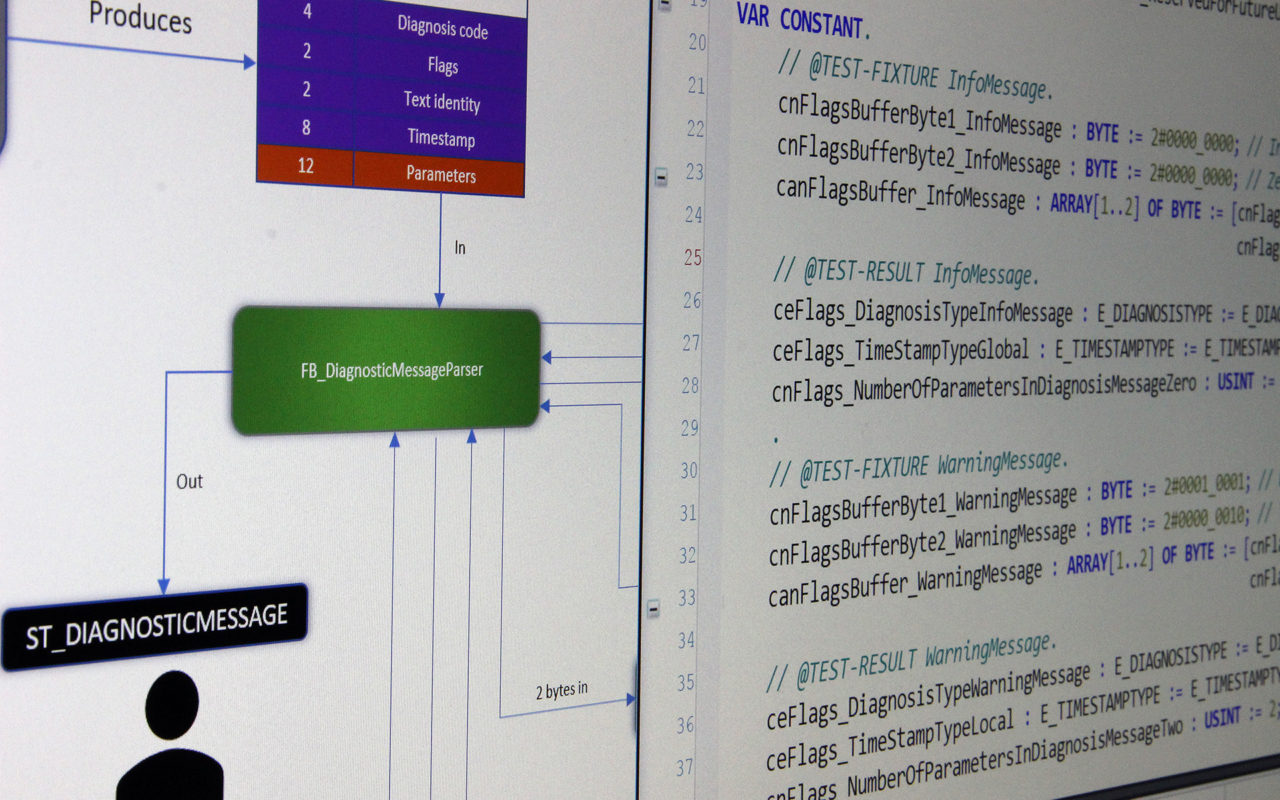
Now, let’s create the headers for all the function blocks that we will write unit tests for. What we’ll do is to create a function block for parsing each and one of the parameters (a total number of four), and an additional function block that uses all these four separate function blocks to deliver the result in the struct ST_DIAGNOSTICMESSAGE. A rudimentary scheme for this looks like follows:
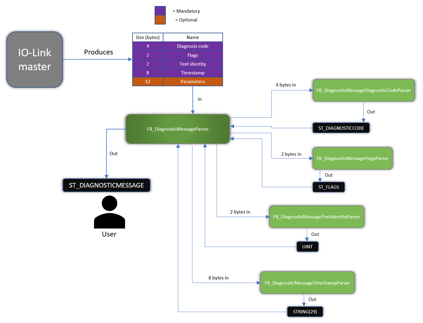
Function block layout
Note that we at this stage are not implementing the function blocks, we’re only stating what functionality they must provide, by declaring their interfaces. As this example is quite simple, we’ll solve that for every function block by making them provide a function block output. But as I’ll talk about later, what you normally want to do is to make use of the interface functionality for function blocks in TwinCAT 3. The function blocks and their headers will have the following layout:
Main diagnosis message event parser
FUNCTION_BLOCK FB_DiagnosticMessageParser
VAR_INPUT
    anDiagnosticMessageBuffer : ARRAY[1..28] OF BYTE;
END_VAR
VAR_OUTPUT
    stDiagnosticMessage : ST_DIAGNOSTICMESSAGE;
END_VAR
This takes the 28 bytes that we receive from the IO-Link master, and outputs the complete diagnostic message according to the layout of our struct ST_DIAGNOSTICMESSAGE described earlier. Note that in this example we’ll only make use of the first 16 (mandatory) bytes, and ignore the 12 (optional) bytes.
Diagnostic code parser
FUNCTION_BLOCK FB_DiagnosticMessageDiagnosticCodeParser
VAR_INPUT
    anDiagnosticCodeBuffer : ARRAY[1..4] OF BYTE;
END_VAR
VAR_OUTPUT
    stDiagnosticCode : ST_DIAGNOSTICCODE;
END_VAR
This function block takes four of the 28 bytes as input and outputs the diagnostic code according to the layout of our struct ST_DIAGNOSTICCODE described earlier.
Flags parser
FUNCTION_BLOCK FB_DiagnosticMessageFlagsParser
VAR_INPUT
    anFlagsBuffer : ARRAY[1..2] OF BYTE;
END_VAR
VAR_OUTPUT
    stFlags : ST_FLAGS;
END_VAR
This function block takes two of the 28 bytes as input and outputs the flags according to the layout of our struct ST_FLAGS described earlier.
Text identity parser
FUNCTION_BLOCK FB_DiagnosticMessageTextIdentityParser
VAR_INPUT
    anTextIdentityBuffer : ARRAY[1..2] OF BYTE;
END_VAR
VAR_OUTPUT
    nTextIdentity : UINT;
END_VAR
This function block takes two of the 28 bytes as input and outputs the text identity as an unsigned integer according to the description earlier.
Timestamp parser
FUNCTION_BLOCK FB_DiagnosticMessageTimeStampParser
VAR_INPUT
    anTimeStampBuffer : ARRAY[1..8] OF BYTE;
    bIsLocalTime : BOOL;
END_VAR
VAR_OUTPUT
    sTimeStamp : STRING(29);
END_VAR
This function block takes eight of the 28 bytes as input and outputs the timestamp as a human-readable string. Note that we also have a bIsLocalTime input, as we want to have different handling on the parsing of the timestamp depending on whether the timestamp is a local or global time stamp. This could be handled in many ways, but for the sake of this example we’ll handle the timestamp as:
- If it’s global, the timestamp is based on the DC-clock of the system and we’ll make use of/parse the eight bytes
- If it’s local, we ignore the eight bytes and instead return the current task DC time
Although this text is about unit testing, I again want to point out that we could handle this differently in such a way that if the timestamp is local, we could read-out the local time of the EtherCAT slave/IO-Link master (if available, located in CoE object 0x10F8), and then calculate what the global time stamp is by calculating the age of the message, and subtracting this from the current DC-time.
And that’s it! Now we have prepared all the data types and function blocks that together form the functionality specification of our parser. What’s nice about this is that we now have formed the acceptance criteria for the expected functionality, which are all the outputs of the function blocks. If we run our function blocks now with real input, they will of course not return the correct values. Everything returned will just be with the default values of the different structures. Our next step will be to write the unit tests that will make our tests fail, and once that is done (and not before!), we’ll write the actual body (implementation) code for the function blocks.
Coding icon by Freepik from www.flaticon.com
This is awesome! Looking forward to the series.
Thanks Peter! Next part of this series is published Thursday 16’th Nov. Stay tuned!
Awesome,
Hoping to use some of these testdriven techniques in the near future for my own project.